
Quick Answer: Series or Side-Stream?
In a full-flow (in-line) polyphosphate feeder, all of the water in the line passes through the phosphate bed. In a bypass (side-stream) feeder, only a controlled fraction of the flow is diverted through the bed and then recombined with the untreated remainder downstream. That single hydraulic difference determines almost everything else: where pressure loss appears, how the dose is controlled, how sensitive the installation is to changing flow rates, and how the unit is adjusted and verified in service.
Neither arrangement is automatically better. The correct choice depends on the line size, the peak and minimum flow, the acceptable pressure drop, how stable the flow is, how precisely the phosphate residual has to be held, and what the treated water is used for.
First, Separate the Duty From the Hardware
Polyphosphate media is normally used for scale inhibition — a threshold or sequestration effect that interferes with the growth of calcium carbonate crystals — and in some systems for corrosion control in metal piping. It is not the same as:
- Water softening, which removes hardness ions by ion exchange. Polyphosphate does not remove hardness, and a hardness test will not drop because a feeder is installed.
- Scale removal, which requires cleaning or descaling of an existing deposit. A feeder is generally used to help prevent new deposition, not to dissolve what is already there.
- Filtration, which removes suspended solids. A phosphate bed is not a filter medium.
- Disinfection. Polyphosphate has no biocidal function.
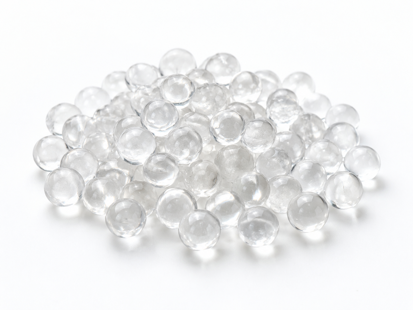
It is also worth being precise about names. “Siliphos” is a trade designation associated with a specific family of glassy polyphosphate spheres, and glassy polyphosphate beads, granular phosphate crystal products, and other polyphosphate media are not guaranteed to be chemically identical. Dissolution behaviour, particle form, and regulatory listings can differ between products that look the same in a catalogue photo. Ask for the actual material description rather than relying on the generic label.
How a Full-Flow Feeder Is Built
The full-flow design places the media chamber directly in the main line, so the entire flow passes through the bed. The water contacts the phosphate for the full residence time offered by the bed volume and the instantaneous flow rate.
Design consequences follow from that:
- Pressure drop sits on the whole stream. The bed, the housing internals, and the connection size all contribute. On small service lines this is often acceptable; on large mains it can become the limiting factor.
- The bed sees the full flow velocity. At high or fluctuating velocities, media can fluidise, attrit, channel, or migrate. Feeders are therefore usually sized against peak flow, not average flow, and the media is selected with an appropriate particle size and bed depth.
- Residual concentration is not fixed. Release depends on flow velocity, contact time, water temperature, and the dissolution characteristics of the specific medium. A feeder does not behave like a metering pump.
- Adjustment is limited. There is usually no dosing valve to trim; the main variables are media choice, bed volume, and where the unit is installed.
How a Bypass Feeder Is Built
A bypass feeder takes a side stream. Part of the flow is pushed through the media chamber, and the treated side stream rejoins the main line at a mixing point. The phosphate concentration in the blended water depends mainly on the concentration leaving the media chamber and the proportion of flow that was diverted.
Two families of bypass design are common:
- Manual bypass. A needle valve or throttling valve sets the diverted fraction. This works reasonably well when the total flow is stable, but the setting must be re-checked and re-trimmed if flow changes seasonally or with occupancy.
- Proportional bypass. A fixed orifice, venturi, or pressure differential across a fitting drives the side stream so that the diverted flow tends to track the main flow. This is a more repeatable approach on lines with varying demand, but it still needs verification with a phosphate test.
Because the media chamber carries only part of the flow, a bypass feeder can be much smaller than the main line. That is why bypass arrangements are common on larger mains where a full-flow bed would create too much head loss or be impractically large.
Design Comparison
| Design factor | Full-flow (in-line) | Bypass (side-stream) |
|---|---|---|
| Hydraulic path | All water passes through the media bed in series | A fraction of the flow is diverted in parallel and re-mixed downstream |
| Where pressure loss appears | On the entire stream, across the bed and housing | Mainly on the diverted stream; the main line sees only the fitting, orifice, or valve restriction |
| Dose control | Set by media type, bed volume, and contact time — no trim valve | Set by the diverted fraction (valve setting or orifice/venturi ratio) |
| Sensitivity to flow variation | Residual drifts with velocity and contact time | Depends on design: manual setting drifts with flow; proportional designs track better |
| Velocities inside the bed | Full line velocity; higher risk of fluidisation, channeling, or media carry-over | Lower, more controlled velocity in the chamber |
| Size relative to the line | Chamber generally matched to line size and rated flow range | Small chamber can serve a much larger main |
| Mixing | Not applicable — the whole stream is treated | Critical: poor mixing means uneven phosphate concentration downstream |
| Verification | Sample downstream of the unit | Sample well downstream of the mixing point, after full turbulence |
| Typical maintenance tasks | Media replacement, inlet strainer cleaning, pressure check | Media replacement plus periodic re-trimming of the bypass and residual testing |
Table entries describe general design behaviour. Actual flow rating, pressure loss, contact time, and media life must come from the feeder and media supplier for the exact configuration being installed.
Mixing and Verification Are Not Optional on a Bypass Feeder
The most common field problem with bypass feeders is not the feeder itself — it is inadequate mixing or a bypass setting that no longer matches the flow. If the treated side stream enters a dead leg or a slowly moving section of main, phosphate concentration can be high at the injection point and near zero further along the line, so pipework protected in one area still scales in another.
Two practical rules help:
- Introduce the treated side stream where the main flow is turbulent and continuous, and sample for residual well downstream of that point rather than at the injection tee.
- Verify with an appropriate phosphate test after commissioning, after any change to the bypass setting, and periodically during operation — not only when a scale problem appears.
Choosing Between the Two Arrangements
Full-flow is usually the better fit when:
- All water in the line needs protection, such as a point-of-entry installation serving a building.
- Flow is relatively constant and within the rated range of the feeder.
- The acceptable pressure loss on the line can accommodate the bed.
- You want simple commissioning and a single sampling point.
Bypass is usually the better fit when:
- The main is large, or the flow is too high for an in-line bed with acceptable pressure loss.
- Only a branch — boiler make-up, a specific process line, or one riser — needs treatment.
- Flow is stable enough for a manual setting, or a proportional (orifice/venturi) design can be used.
- Someone on site can test and re-trim the residual as conditions change.
What to Confirm Before Ordering
Polyphosphate feeders are sized on real conditions, not on pipe diameter alone. Gather the following before requesting a recommendation:
- Source-water analysis: total hardness, pH, alkalinity, temperature range, and any iron or manganese.
- Flow data: minimum, normal, and peak flow, plus how often flow stops completely.
- Line details: pipe size and material at the intended installation point, and available pressure.
- Treatment objective: scale inhibition, corrosion control, or both — and where the protected equipment sits in the system.
- System context: whether softening, carbon, filtration, or UV is installed, and in what order.
- Media questions: exact chemistry and form, dissolution characteristics, and any listing that applies to the product for the intended use.
- Regulatory position: potable-water requirements and any local restrictions on phosphate discharge to drains or waterways.
A “food grade” description alone does not make a product suitable for drinking water. Potable-water suitability has to be verified for the exact product, the application conditions, and the destination market. The same applies to discharge: polyphosphate is a nutrient, and some regions restrict its use or disposal, so confirm local requirements before specifying a feeder.
Common Design Mistakes
- Sizing a full-flow unit on average flow. Peak flow governs pressure loss and media behaviour.
- Assuming a bypass feeder treats all the water. Only the diverted fraction contacts the media; the rest is treated by dilution and mixing.
- Installing downstream of media that removes or consumes phosphate, such as activated carbon, and then finding no residual at the tap.
- Expecting softened water. Hardness remains; the mechanism is inhibition, not removal.
- Setting the bypass once and never testing again. Seasonal flow changes quietly change the dose.
- Ignoring stagnation. Long no-flow periods can allow the water sitting in contact with the media to become more concentrated than during normal operation, so the first water drawn may differ from steady-state conditions.
- Overlooking temperature. Dissolution generally increases with water temperature, so a feeder placed on a hot line behaves differently from one on the cold feed.
Frequently Asked Questions
Can a bypass feeder be used on a line with highly variable flow?
Only if the design provides proportional dosing. A manually set valve assumes a roughly stable total flow; where demand swings widely, the phosphate residual will swing with it unless the setting is adjusted or a proportional orifice/venturi arrangement is used.
Does a full-flow feeder deliver a constant phosphate concentration?
No. Concentration depends on flow velocity, contact time, water temperature, and the dissolution behaviour of the specific medium. Full-flow construction removes the bypass-variable, but it does not turn the feeder into a metering device.
Can a polyphosphate feeder replace a water softener?
No. A softener removes hardness ions by ion exchange. A phosphate feeder inhibits scale formation and can help control corrosion, but the water remains hard and the hardness reading will not change.
Where should the feeder be installed?
Typically on the cold feed, upstream of the equipment being protected and downstream of any treatment that would remove or consume phosphate. Confirm the arrangement, temperature limits, backflow protection, and any sampling point requirements with the supplier and the local authority.
What media should be specified?
That depends on the feeder design, the water chemistry, and the required residual. Glassy polyphosphate beads, granular crystal products, and other forms are not interchangeable in every feeder, so specify the form the feeder is rated for and ask for documented dissolution and approval information.
Requesting a Recommendation
If you are selecting between a full-flow and a bypass polyphosphate feeder for a specific project, ENVO CHEMICAL can review the application against the media and feeder configuration involved. To make the reply useful, include: the installation point and line size, minimum and peak flow, source-water hardness, pH and temperature, the treatment objective (scale inhibition, corrosion control, or both), any upstream or downstream treatment equipment, the required specification, quantity, and destination market. With those details, the hydraulic arrangement can be matched to the duty rather than chosen by habit.
