
Start With the Chemistry, Not the Pipes
You can trace polyphosphate-treated water through a building without cutting into walls or trusting faded valve tags, because the treatment leaves a measurable marker in the water itself. The practical method is to confirm the phosphate residual at each outlet and work backwards through the valves, one at a time, documenting what each valve actually controls. That combination — a chemical tracer plus a controlled isolation test — answers the two questions unlabeled valves always raise: which outlets receive treated water, and which valve isolates which zone.
This matters because polyphosphate media is often installed once and then forgotten. A building can have a dosing housing on the incoming main, a partially open bypass beside it, and thirty unlabeled gate valves feeding risers nobody has mapped in fifteen years. Before ordering replacement media or promising a tenant that scale control is active on a given line, someone has to prove where the treated water actually goes.
What the Treatment Actually Adds to the Water
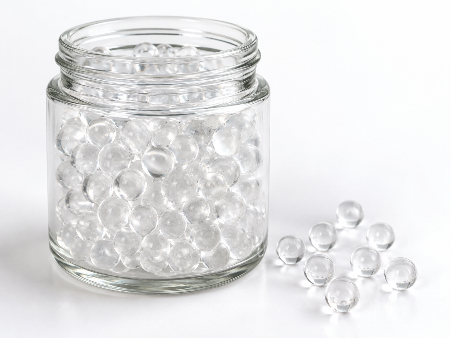
Slow-dissolving polyphosphate media — the glassy, spherical type often sold under trade names such as Siliphos — releases condensed phosphate species as water passes through the housing. Those species interfere with the growth of carbonate scale crystals and can form a thin protective film on metal surfaces. That is a scale-inhibition and film-forming function. It is not water softening: hardness minerals stay in the water. It is not filtration: sediment and chlorine are untouched. It is not scale removal: existing deposits are not dissolved. It is not disinfection.
Because the mechanism is chemical rather than mechanical, a treated line carries a small phosphate residual that an untreated line does not. That residual is your tracer — provided you know what the incoming water already contains.
One caution applies throughout: not every product described as “siliphos crystal,” “phosphate crystal,” or “polyphosphate media” behaves identically. Some are slow-dissolving condensed phosphate glasses, some are blended ortho/polyphosphate formulations, and some are silicate-based products with different chemistry. The tracer method below works for phosphate-bearing media. Confirm the chemistry of the specific product installed before relying on a phosphate test alone.
Step 1: Establish the Source-Water Baseline Before Touching Anything
Sample the incoming mains upstream of the treatment housing, then sample immediately downstream of the housing while water is flowing. Record both values, the time, the flow condition, and the test method. Without this baseline, every later reading is guesswork.
The baseline matters more than most people expect. Many municipal supplies already contain phosphate added by the utility for corrosion control — sometimes orthophosphate, sometimes blended phosphates. If the incoming water already carries a phosphate residual, the incremental signal from a point-of-entry treatment unit may be small, and a mid-range test kit will not resolve it. In that situation, the tracing plan needs a lower-range method or a different tracer.
Step 2: Choose a Tracer That Matches the Product and the Question
| Method | What it proves | Main limitation |
|---|---|---|
| Colorimetric orthophosphate test (molybdate/ascorbic acid type) | Treated water is present at that outlet when the sample was taken | Only reads orthophosphate; condensed polyphosphates must be converted first. Needs a low-range kit to see small residuals. |
| Total phosphate test with acid hydrolysis or persulfate digestion | Detects condensed phosphates that a direct orthophosphate reading would miss | Slower, needs a digestion step; usually a lab or a kit with digestion capability |
| Food-grade tracer dye with UV or visual detection | Follows the actual path of water and reveals unmapped connections | Requires dye approved for potable-water contact and, where the system serves drinking water, confirmation from the local authority. Does not prove the media is still active. |
| Valve isolation with flow confirmation at fixtures | Which valve controls which outlets | Slow, needs two people, and dead legs or cross-connections can mislead |
| Acoustic or electronic pipe location | Where concealed pipe runs | Unreliable on plastic pipe, and tells you nothing about whether water is treated |
In most buildings, the phosphate residual test does the heavy lifting and the isolation test supplies the valve map. Dye is a useful tiebreaker when two branches show nearly identical residuals and you need to know which one feeds a specific fixture.
Expect the expected residual range to be low. Ask the media or equipment supplier what residual their product is designed to produce under your flow conditions, and select a test kit with enough resolution to see it. A kit that reads 0–50 mg/L tells you almost nothing about a small treatment residual.
Step 3: Map the Hydraulics Before You Turn a Single Valve
Walk the mechanical room and write down what you find. This takes twenty minutes and prevents a day of confusion.
- Treatment unit location — point of entry, or a branch serving only part of the building?
- Bypass arrangement — is there a bypass loop, and is the bypass valve fully closed? A partly open bypass blends treated and untreated water and produces weak, inconsistent residuals downstream.
- Cold-only or whole-building feed — if the housing sits upstream of the water heater, hot outlets will also carry residual. If it sits on a cold branch only, hot water will read at baseline.
- Pressure-reducing valves, backflow preventers, check valves — these break the hydraulic continuity assumptions used in simple isolation tests.
- Hot-water recirculation loops — a recirculating loop distributes residual quickly but can also return water from unexpected zones.
- Isolation valves between risers — the ones that connect two zones and are never quite shut.
- Abandoned or capped lines — dead legs hold old water and will read either high or low, depending on age and temperature.
Step 4: Run the Isolation Test With Two People
A single person walking between a basement valve and a fourth-floor fixture cannot distinguish a valve effect from normal pressure variation. Use two people in contact by phone or radio: one at the valve manifold, one at the fixtures with a test kit and a stopwatch.
- Open a fixture, let it run long enough to clear the volume held in the branch, then sample. Record the phosphate value.
- Close one valve at the manifold. Keep the fixture running and sample again after the same flush interval.
- A drop to baseline confirms that valve feeds that outlet. No change means it does not.
- Reopen the valve and move to the next fixture or the next valve. One variable at a time.
Flush volume, not flush time, is what matters. Estimate the pipe volume between the valve and the fixture and run at least two to three times that volume before sampling. In long horizontal runs or large-diameter risers, this can take several minutes.
Reading Mixed or Ambiguous Results
- Residual falls gradually along a branch — an unmapped connection or a large dead leg is diluting the treated water.
- Residual present at cold outlets, absent at hot — the treatment unit is downstream of the water heater, or the hot loop is fed from a separate untreated source.
- Residual present everywhere but weaker than expected — check the bypass valve and the actual flow rate through the housing. High flow through undersized media contact time reduces dissolution.
- Residual present in hot water but not cold — condensed phosphates hydrolyze to orthophosphate faster at higher temperatures. A direct orthophosphate reading on a hot sample can overstate the treated fraction unless you also measure total phosphate.
- No residual anywhere — confirm the baseline again. If the utility already doses phosphate and the reading never changes, the media may be exhausted, channeled, or bypassed entirely.
Step 5: Label, Record, and Keep the Map Alive
Tag valves as you confirm them, using a scheme that survives staff turnover: zone, riser, and fixture group — for example, R-3 North / WC-2 Floors 5–8. Print the tags; do not rely on marker on a dusty pipe. Keep a one-page valve schedule with the date of the survey, the tester’s name, the test method, and the baseline value recorded at the time.
Note on the schedule which outlets are confirmed treated, which are confirmed untreated, and which remain uncertain. Uncertainty is a legitimate result and is far more useful than a guess, especially if the building serves drinking water and someone later wants to know whether a given tap is downstream of the treatment unit. Drinking-water suitability depends on the exact media, the application conditions, and the destination market’s rules — treat the survey map as hydraulic information, not as a compliance document.
Common Mistakes That Waste a Day
- Using a high-range test kit on a low-residual application.
- Sampling immediately after opening a tap, before the branch has been flushed.
- Assuming a phosphate reading proves the media is still working — it proves treated water reached that point, not the dosage.
- Confusing polyphosphate treatment with softening, and testing hardness instead of phosphate.
- Ignoring utility-added phosphate in the incoming supply, then chasing a phantom cross-connection.
- Testing with dye in a potable system without confirming that the dye is approved for potable-water contact in that jurisdiction.
Frequently Asked Questions
Can I trace treated water with a hardness test instead of a phosphate test?
No. Polyphosphate media does not remove hardness, so total hardness stays essentially unchanged across the treatment unit. Hardness is the right test for a softener, not for a polyphosphate dosing point.
Will a TDS meter show the difference?
Not usefully. The phosphate contribution is too small to separate from normal variation in total dissolved solids.
How long does treated water take to reach a distant outlet?
It depends entirely on pipe volume, flow rate, and how much untreated water sits in the branch. Measure it during the isolation test rather than assuming a fixed time.
The building has a bypass around the treatment housing. Should I close it?
Close it only after confirming that doing so does not leave any zone without supply, and only with the building owner’s approval. Once closed, re-run the outlet tests — residuals downstream should rise if the bypass was the dilution source.
Turning the Survey Into a Specification
The survey output — flow through the housing, baseline and downstream residuals, which zones are confirmed treated, and how the media is performing at current flow — is exactly what determines whether the existing media grade and housing size are still appropriate. If residuals have dropped across all confirmed outlets while flow and baseline are unchanged, the media is a likely cause and replacement or a chemistry review is the next step.
If you are specifying replacement media for a mapped system, ENVO CHEMICAL can review the details with you. Send the building and system type, whether the treated water is potable or process water, the source-water analysis including any phosphate already present, the housing model and measured flow, the media currently installed, the residual range you need to achieve, quantity, and destination market. With that information, the appropriate product form and specification can be discussed against your application rather than in general terms.
