
Start With the Measurement, Not the Loop
Measuring calcium carbonate deposition in a polyphosphate test loop is mainly a sensitivity problem. Polyphosphate media are usually evaluated for scale inhibition — the ability to keep calcium carbonate from crystallising on a hot surface — and the effect being measured is often small, gradual, and easy to lose inside the noise of the loop itself. Before selecting pumps, heaters, or coupons, decide what quantity you will actually report and whether your method can resolve it.
Three decisions drive everything else:
- The deposition surface. A heated metal tube, a heated coupon, or an unheated immersed coupon behave differently and produce different numbers.
- The measurement principle. Gravimetric mass, calcium mass balance, heat-transfer fouling resistance, and electrochemical techniques answer slightly different questions.
- The phosphate chemistry. Polyphosphate is not an inert tracer. It dissolves, hydrolyses toward orthophosphate, and can form its own calcium salts, so it interferes with both the loop chemistry and some analytical methods.
A useful test loop result states four things together: how much deposit formed, on what surface area, under what thermal and hydraulic condition, and in what water chemistry. A deposition number without those four is not reproducible and cannot be compared with another laboratory’s data.
Four Ways to Measure Calcium Carbonate Deposition
Each method below measures a different physical quantity. None of them is universally “best”; the right choice depends on the expected deposit mass and the purpose of the test.
1. Gravimetric deposit mass
Weigh the coupon or heater tube before and after the run, dry it under defined conditions, and report mass gain per unit area (commonly mg/cm² or g/m²). This is the most direct and widely used method for coupon-style loops.
Practical points:
- Use an analytical balance with resolution well below the expected mass gain. If a run produces 2 mg of deposit, a 0.1 mg balance gives poor relative precision.
- Define drying: temperature, time, and desiccant. Calcium carbonate deposits retain water and can also pick up atmospheric moisture, so an inconsistent drying step can shift results by more than the treatment effect.
- Post-run handling matters. Removing a coupon, rinsing it, and transporting it can detach loosely adherent deposit. Decide in advance whether the reported value is total mass or firmly adherent mass, and say so.
- A surface that has been cleaned but not passivated may gain mass faster in the first hours than a stabilised surface does. Run a blank to see how much of the mass gain is surface conditioning rather than scaling.
2. Calcium mass balance across the loop
Measure calcium concentration entering and leaving the test section, multiply the difference by flow rate and time, and convert to an equivalent mass of calcium carbonate. This approach is attractive because it does not require removing or weighing the deposit.
Its main limitation is that it measures calcium loss from solution, not deposition on a surface. Calcium that leaves solution can end up in three places:
- on the heated or unheated test surface (the target);
- as suspended particles in the reservoir or bulk water;
- as loose sediment in low-velocity zones, filters, or tubing.
In a recirculating loop, bulk precipitation and settling can dominate the mass balance while contributing little to surface fouling. If you use this method, pair it with a filter or settling measurement so the two fractions can be separated, and report them separately.
3. Heat-transfer fouling resistance
When the objective is to predict performance of a heat exchanger, the meaningful output is not deposit mass but the loss of heat transfer. As scale builds on a heated surface, the overall heat transfer coefficient falls. Fouling resistance is typically calculated as:
Rf = (1 / Ufouled) − (1 / Uclean)
This requires accurate measurement of heat flux, wall temperature, bulk temperature, and flow rate, and it needs a clean baseline on the same loop. Its advantage is that it is continuous and non-destructive, so you can see the shape of the fouling curve rather than only an end-point mass. Its disadvantage is that it is an indirect measurement: an increase in Rf tells you a deposit is forming but not what the deposit is made of.
Bulk temperature drift, flow oscillations, and fouling on the reference side of a heat exchanger all appear as apparent scaling and must be controlled or corrected.
4. Continuous electrochemical and mass-sensitive sensors
Quartz crystal microbalance, electrochemical impedance spectroscopy, and chronoamperometric techniques can detect deposition in real time on a small sensing surface. They are useful for ranking treatments quickly and for capturing the induction period before deposition becomes visible. They are less useful for predicting full-scale heat exchanger behaviour, because the sensing surface, its roughness, and the local shear are not the same as those of an industrial tube. Treat these results as comparative indices, not as absolute deposition rates.
Confirming the deposit is calcium carbonate
Weight gain on a coupon is not proof of calcium carbonate. Iron oxide, calcium phosphate, silica, and organic material can all deposit under the same conditions. Composition should be checked by at least one of the following:
- acid dissolution of the deposit followed by calcium analysis (EDTA titration, ICP-OES, or a colorimetric method);
- X-ray diffraction to identify calcite, aragonite, vaterite, or non-carbonate phases;
- scanning electron microscopy for morphology, which is also a useful indicator of whether a polyphosphate is distorting crystal growth or simply dispersing particles.
This step is especially important in polyphosphate work. Phosphate can be incorporated into the deposit, so a calcium-only analysis may overstate the carbonate fraction.
Comparing the Methods
| Method | What it measures | Real-time? | Main source of error |
|---|---|---|---|
| Gravimetric mass | Total deposit mass on a defined area | No | Drying and handling losses; small mass relative to balance precision |
| Calcium mass balance | Calcium removed from solution | No (by sampling interval) | Bulk precipitation and settling counted as surface deposition |
| Fouling resistance | Loss of heat transfer | Yes | Drift in baseline, flow, or temperature |
| Electrochemical / QCM sensors | Deposition on a sensing surface | Yes | Sensor surface not representative of the real tube |
Mass and thickness are related only through deposit density and porosity. Using pure calcite bulk density (about 2.71 g/cm³) as a rough conversion, 1 g/m² corresponds to approximately 0.37 µm of thickness, and 1 mg/cm² to roughly 3.7 µm. Real deposits are porous and may contain other phases, so use these figures only for order-of-magnitude comparisons, never as a substitute for measurement.
Loop Design Factors That Change the Result
Thermal condition
Calcium carbonate becomes less soluble as temperature rises, which is why deposition concentrates on heated surfaces in real equipment. A loop with no heated surface will usually deposit much more slowly and may rank treatments differently from one with a controlled heat flux. If you use heating, record surface temperature or heat flux — not just bulk temperature — because that is what the deposit actually experiences.
Hydraulics
Higher velocity increases shear at the wall and generally reduces deposition. A loop run at low velocity can show heavy scaling that would not occur at the velocity of the real system. Report velocity or Reynolds number in the test section, not just volumetric flow, because flow alone means nothing without the tube diameter.
Water chemistry
Record calcium hardness, total alkalinity, pH, conductivity or TDS, temperature, and (where relevant) sulfate and silica. The scaling driving force should be expressed with an index such as the Langelier Saturation Index or a calcium carbonate precipitation potential, with the calculation method stated. Two labs can agree on pH and hardness and still disagree on scaling tendency if they compute saturation differently.
Because a recirculating loop changes chemistry over time — calcium is consumed, pH drifts as CO₂ is lost or gained, and phosphate accumulates — either use a reservoir large enough relative to the deposit mass, continuously replenish with controlled makeup water, or operate once-through. Sampling should also be at defined points, since a sample drawn near the heater is not the same as a sample from the reservoir.
Polyphosphate dosing and stability
Polyphosphate dissolves gradually, so the concentration entering the test section is not constant unless you control it. Measure both total phosphate and orthophosphate, and report which species was dosed. Hydrolysis converts polyphosphate to orthophosphate over time; orthophosphate behaves differently as a scale inhibitor and can form calcium phosphate under conditions where polyphosphate would not. A test that does not distinguish the two cannot explain its own results.
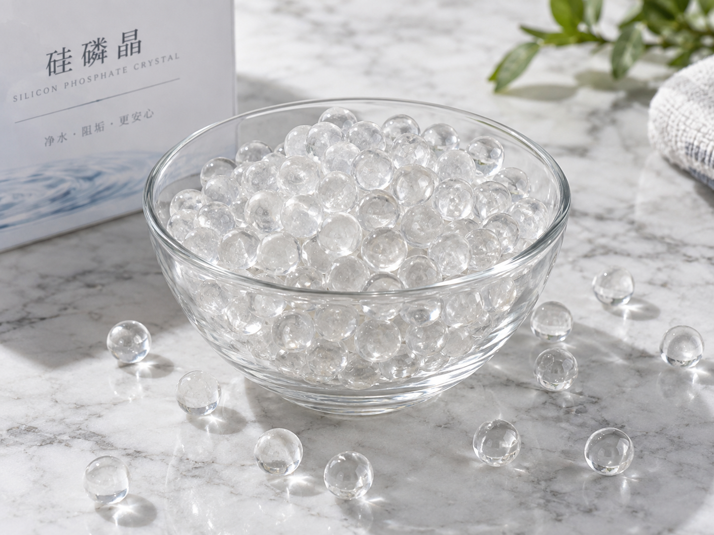
It is also worth noting that products sold as Siliphos, siliphos crystal, phosphate crystal, and generic polyphosphate media are not necessarily equivalent. Composition, dissolution rate, and phosphate chain-length distribution differ by supplier, and these differences affect both the release profile and the deposition measurement. A loop result belongs to the specific material tested, identified by its datasheet, not to the product category.
Quality Control That Makes the Data Defensible
- Blank run. Same water, same loop, same duration, no polyphosphate. Without it you cannot separate treatment effect from surface conditioning and baseline scaling.
- Duplicate or triplicate runs. Report the mean and the spread. A single coupon result is an observation, not a measurement.
- Recovery or verification check. Confirm your analytical method recovers known calcium concentrations in the loop’s background matrix, which may contain phosphate and dispersants.
- Consistent cleaning protocol. If coupons are reused, define how they are cleaned and verify that the surface is restored to the same baseline mass.
- Detection limit. State the smallest deposit mass your method can reliably distinguish from zero, and make sure the run is long enough to exceed it by a comfortable margin.
Reporting a Result Another Lab Can Reproduce
A complete report includes: loop configuration and materials; test surface material, area, and roughness; flow velocity or Reynolds number; bulk and surface temperature or heat flux; run duration; full water chemistry at start and end; saturation index and calculation method; polyphosphate product identity, dose or dissolution condition, and total/orthophosphate measurements; measurement method, drying or stripping procedure, and detection limit; blank result; and a composition check of the deposit. If any of these is missing, comparisons across studies become unreliable.
Frequently Asked Questions
Can I measure deposition without heating the test surface?
Yes, but deposition will be slower and the ranking of treatments may differ from a heated system, because temperature is a primary driver of carbonate scaling. An unheated coupon loop is a reasonable screening tool; it is a weaker predictor of heat exchanger fouling.
How long should a polyphosphate test loop run?
Long enough for the deposit to exceed your method’s detection limit by a clear margin. Run the blank first — it tells you the baseline scaling rate under your conditions, from which the required duration can be estimated. There is no universal duration.
Does weight gain prove the deposit is calcium carbonate?
No. Confirm with acid digestion plus calcium analysis, and preferably with XRD or SEM. Phosphate, iron, silica, and organic deposits can all add mass.
Is a polyphosphate test loop measuring water softening?
No. Threshold scale inhibitors such as polyphosphates interfere with crystal growth; they do not remove hardness ions from water the way an ion exchange softener does. A calcium mass balance showing a concentration change is evidence of precipitation, not of softening capacity.
Can two polyphosphate materials be compared in the same loop?
Only with a full clean and re-baseline between runs, because residual phosphate on tubing and surfaces carries over. Cross-contamination is one of the most common reasons a comparison shows a difference that does not exist.
Selecting Polyphosphate Material for a Test Programme
If the loop is being built to evaluate a specific polyphosphate crystal for a filter housing, a dosing cartridge, or an industrial water line, the material should be specified by its measured release behaviour rather than by a generic category name. ENVO CHEMICAL can discuss the technical information available for the polyphosphate materials relevant to your test conditions.
To make that discussion useful, please share: the application and equipment type, the source-water analysis (hardness, alkalinity, pH, temperature, TDS), the target of the test (scale inhibition, fouling resistance, or dissolution rate), the loop or system conditions, the specification or grade you are considering, the quantity required, and the destination market. With those details, the appropriate product information and any constraints on drinking-water or other regulated applications can be confirmed rather than assumed.
