
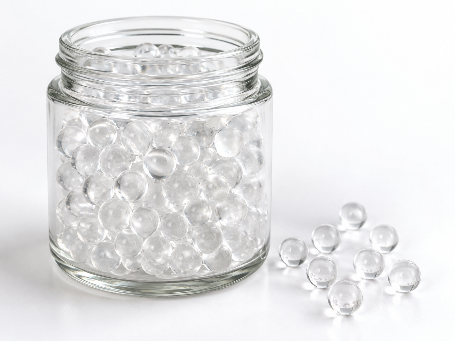
A test connection and an operational bypass look similar on a drawing and even more similar in a crowded skid, but they exist for opposite reasons. A test connection is a small-bore, intermittent diagnostic point used to draw a water sample. An operational bypass is a full-bore process line that lets water move around the polyphosphate media vessel — for maintenance, for commissioning, or for deliberate blending. Confusing the two is one of the most common causes of meaningless phosphate readings and of untreated water quietly slipping past the media for months.
The practical rule is simple: separate them by function, by pipe size, by valve type, by position in the flow path, and by tag name on the P&ID. Then make the sample point sit downstream of any legitimate blend point so the sample reflects what the system actually delivers.
What each connection is actually for
Polyphosphate media — including slow-dissolving polyphosphate crystal and silicate-phosphate glass sold under trade names such as Siliphos — works by dissolution, not by ion exchange. As water passes through the bed, a small amount of polyphosphate enters solution and interferes with calcium carbonate crystal growth downstream, which is scale inhibition at threshold dose rather than water softening. Some formulations also lay down a thin film on metal surfaces that is described as mildly corrosion-inhibiting.
Because the mechanism depends on contact with the media, anything that routes water around the vessel changes the chemistry of the water leaving the skid. That is why the bypass is a process component and the sample point is an instrument component, and why they should never be the same fitting.
| Attribute | Test connection | Operational bypass |
|---|---|---|
| Purpose | Draw a representative sample for analysis | Route water around the media vessel |
| Flow | Intermittent, brief, small volume | Continuous or extended, potentially full system flow |
| Typical bore | Small (often a few millimetres) | Same as the main process line |
| Valve type | Needle or small plug valve, hose barb or quick-connect | Full-port ball or butterfly valve with position indication |
| State in normal operation | Closed except during sampling | Closed, or partially open only if controlled blending is intended |
| Effect on treated-water quality | None when closed; contaminating if left open | Directly dilutes or eliminates the treatment effect |
Why the mix-up causes real problems
A “sample” taken from the bypass header
If the sample valve is tapped into the bypass line, the reading describes untreated or partly treated water. A technician may then increase media volume, change media grade, or replace a perfectly good bed in an attempt to raise a phosphate residual that was never low in the first place.
A sample valve used as a mini-bypass
Small-bore lines pass more water than most people expect, particularly at high mains pressure. A needle valve left slightly open, or a hose barb with the hose removed and the valve forgotten, becomes a permanent uncontrolled bypass. On a low-flow system the leak may be a meaningful fraction of total flow, which quietly reduces the treatment effect while leaving no obvious fault indication.
Dead legs and stagnant sample lines
A sample branch that is long, uninsulated, or routed upward with a trapped volume holds old water. Purging is essential, and the first sample drawn after a long idle period should be discarded. A short, direct tap is easier to purge than a remote panel with several metres of tubing.
Crystal fines and small orifices
Polyphosphate media beds can release fine particles, especially during commissioning or after a media change. Small-bore sampling valves, orifices, and quick-connects are the first places to plug. Design the sample line so it can be flushed and cleaned without dismantling the skid, and place any pre-filter upstream of the media, not in the sample branch.
Commissioning flush mistaken for a permanent bypass
Many skids need a temporary flush path to clear construction debris and media fines before the bed is put into service. If that temporary line stays in place, it becomes an undocumented second bypass. Remove it at handover, or valve it off and tag it clearly as commissioning-only.
How to separate the two in the P&ID and in the field
Route them to different places
The bypass loops around the media vessel and rejoins the main line. The sample connections sit on the main line — one upstream of the vessel as a raw-water reference, and one downstream where the water is fully mixed. Keeping the sample taps off the bypass loop entirely removes the possibility of drawing from the wrong line.
Make the valves look different
Use a full-port, lockable, tagged valve with a visible position indicator for the bypass. Use a small needle or plug valve with a hose barb or quick-connect for the sample point. Different handle shapes and sizes give a visual cue that survives a turnover of maintenance staff.
Label by function, not by number alone
Tags such as “BYPASS — NORMALLY CLOSED” and “SAMPLE — OUTLET, PURGE 2 MIN” prevent more errors than an unannotated valve number. If the skid is controlled by a BMS or SCADA system, consider a position switch on the bypass so an open bypass raises an alarm or appears clearly on the operator screen.
Place the outlet sample downstream of any blend point
This is the single most important layout decision. If controlled blending is part of the design — sometimes used when flow is very low to avoid overtreatment — the bypass tie-in must rejoin the main line before the outlet sample tap. A sample taken upstream of the blend point measures the media bed; a sample taken downstream measures the water the customer receives. Only the second one is a valid compliance or performance sample.
Control backflow and contamination
Fit a check valve in the sample line if there is any chance of downstream pressure exceeding line pressure, and avoid sample points that can siphon from a drain or hose. Never share a sample tap between a treated line and an untreated line.
Commissioning and handover checklist
- Confirm the bypass is tagged, lockable, and shown as normally closed on the as-built drawing.
- Verify the bypass tie-in point is upstream of the outlet sample connection if blending is intended.
- Confirm no sample valve is drilled into the bypass loop.
- Check that all sample lines are short, drainable, and purgeable, with no dead legs.
- Flush each sample point for a defined period and discard the first volume before collecting.
- Record inlet and outlet samples at the same time, at a known flow rate.
- Walk the skid with a torch and confirm every valve is physically in the position the drawing states.
- Remove or permanently valve off any commissioning-only flush line.
- Confirm the sample valves close fully and cannot be left in a partly open position unnoticed.
- Photograph the as-left valve positions and attach them to the handover file.
Test methods and what the numbers mean
Total phosphate is normally measured colorimetrically — for example, by a molybdenum-blue or ascorbic-acid method — and residual hardness by titration. These methods tell you the concentration in the sample; they do not tell you whether the treatment is adequate for the downstream equipment. That judgement depends on the source-water chemistry, temperature, flow, pipe material, and the protection target for the system.
Keep the functional categories distinct when interpreting results:
- Scale inhibition — threshold dosing that slows or prevents mineral deposition on surfaces. This is what polyphosphate media are normally used for.
- Water softening — removal of calcium and magnesium by ion exchange. Polyphosphate media do not do this and do not reduce hardness numbers.
- Scale removal — dissolving existing deposits. This is a different chemical task and is not achieved by passing water through a polyphosphate bed.
- Filtration — physical removal of suspended particles. A polyphosphate vessel may trap some fines, but particle removal is not its purpose.
- Corrosion inhibition — film formation on wetted metal surfaces. Some polyphosphate and silicate-phosphate blends are used for this, but performance depends on formulation and water chemistry.
- Disinfection — inactivation of microorganisms. Polyphosphate media have no disinfection role.
What cannot be assumed for a specific product
Polyphosphate media are not interchangeable. Dissolution rate, useful flow range, contact time, temperature tolerance, pH window, expected service life, and the phosphate residual produced all vary by formulation, particle size, and bed geometry. Siliphos is one trade name for one family of slow-dissolving polyphosphate glass; a generic “phosphate crystal” sold under a similar description may behave differently.
Because of this, the following must be confirmed for the exact product and application rather than copied from another datasheet: allowable flow rate per unit of media, minimum and maximum water temperature, acceptable pH range, target residual at the point of use, replacement or top-up criteria, and any limit on the number of media vessels in series. If a supplier cannot provide these for your water and your flow profile, the skid design is not yet complete.
One further caution: a material described as food grade is not automatically approved for drinking-water contact. Potable-water suitability depends on the exact product, the application conditions, and the regulations of the destination market, and must be verified separately for each.
Frequently asked questions
Can I use the bypass valve to take a sample?
No. A sample drawn from a bypass line describes whatever is flowing through that line, which by definition has not passed through the media. Use a dedicated sample tap on the main line.
Does opening the bypass soften the water?
No. Opening the bypass reduces or eliminates the scale-inhibition effect by sending water around the media. It does not soften water, and it will not lower hardness readings.
Is partial bypass a legitimate operating mode?
It can be, when a system designer deliberately blends treated and untreated water to control residual at very low flow rates. In that case the blend point, the maximum blend ratio, and the sampling location must all be defined in the design documents — not decided on site.
How often should the media be replaced?
Replacement is based on measured performance and observation of the bed, not on a calendar interval. The specific criteria must come from the media supplier and the system designer for your water conditions.
Specifying a polyphosphate skid or replacement media
If you are laying out a new skid or reviewing an existing one, get the connection logic right before sizing anything else: full-bore bypass on the process line, small-bore sample points on the main line, outlet sample downstream of any blend tie-in, and every valve tagged with its normal position. That single discipline removes most of the false readings and hidden bypasses that make polyphosphate treatment look unreliable.
To discuss media selection or skid configuration with ENVO CHEMICAL, send the details that actually affect the answer: the application and whether the water is potable or non-potable, your source-water analysis, peak and continuous flow rates, water temperature and pH, the equipment you are protecting, the target phosphate residual or treatment objective, your intended skid arrangement including bypass and sample points, the media form and quantity you need, and the destination market for regulatory checks.
